
SMC is proud to present in this catalog the widest range of products that exist on the market for electrical test equipment in relay testing and for substations maintenance in applications for generation, distribution, transmission, and industry in general.
For more than 25 years SMC has been designing and manufacturing electrical test equipment for the above electrical sectors. Our permanence in this highly technological and competitive market can be explained thanks to the constant application of working principles, the company structure, and products produced, making us successful during all these years.
Quality is the foundation of our company in all aspects and in all our company departments; R & D, production, sales, and after-sales support.
Quality in Design guarantees that our equipment meets the demands that we impose and what our customers expect
Quality in Products is obtained by taking care of the details during the entire production process and by selecting the best material and components that are used in the equipment.
Quality in Service, with immediate and permanent attention, technical and commercial questions are answered by a qualified and committed persons.
Maximum compliance in the design of our products meets the needs of customers and users worldwide. All our products are flexible in their use, as we incorporate a very intuitive manual control. SMC offers a range of products that meet the application requirements, which is reflected by our satisfied customers who use our products.
At SMC we seek alternatives that make us better, more efficient, more competitive. Therefore, we question every step in the process and every task, no matter how small it is.
Design and innovation are inside our DNA. Formula Innovation is a reflection of who we are, and we have made it real with an unprecedented product: the Raptor.
Our Research and Development department has a commitment to further develop revolutionary new products in the field of power systems testing, focusing on making the job easier for all our customers.
Innovation leads us to the future. Innovation brings us closer to you.

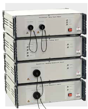
The secondary injection equipment for relay testing has been the main activity of SMC. For this reason, the extensive range of products comes from the experience obtained during the past 25 years. Our tradition in the design and manufacturing of this type of equipment has enabled us to have a complete range of equipment with different philosophies for the various applications and customers who use relay test equipment
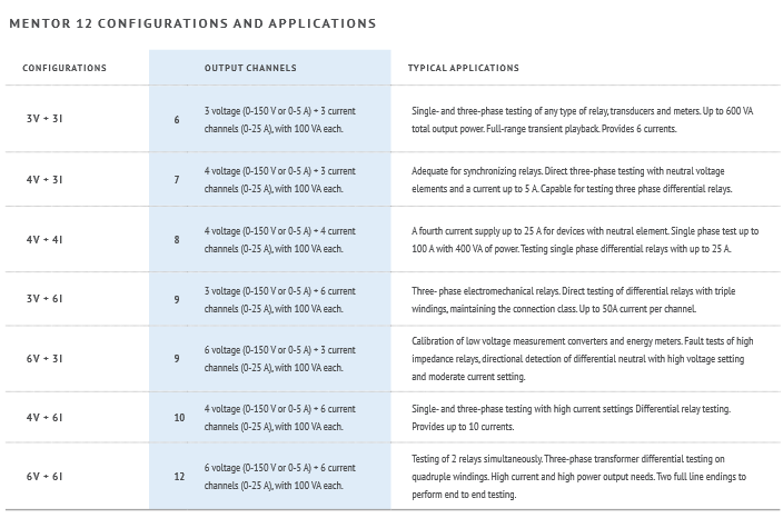
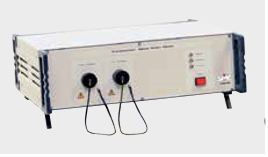
Mentor 12 incorporates the latest designs and concepts in test equipment, based on leading-edge technology. This revolutionary product, the most modern equipment of its class, fulfills the requirements of the transmission departments and for the commissioning of new installations. Unlike any other test equipment, both in power and features, the Mentor 12 can have up to two, three-phase systems in one unit, with all logical inputs and outputs required when testing protection relays. This equipment continues the tradition of SMC in designing the most complete equipment with sufficient, and reversible outputs, along with independent output channels. The ability to upgrade the equipment with Plug and Play additions makes the Mentor 12 the most advanced equipment on the market.
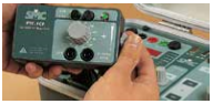
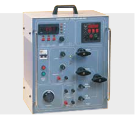
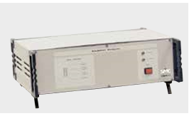
The PTE-100-C is a single-phase test set based on variac output regulation. The outstanding features are; the smallest, lightest, highest power, and easiest to use equipment of its kind on the market. Its versatility is an essential tool for all types of relay tests.
The PTE electronic range of equipment is designed to serve the majority of relay applications and can be combined with other equipment to expand the applications. These portable, robust, equipment have electronic generated outputs and are a favorite with service companies, along with the distribution and generation departments of the Utilities as they are adapted and designed to meet their requirements. The characteristics and the functionality of this range of products are not found anywhere else. Another unique benefit is the high power, both in current and voltage, being able to test all types of relays, including electromechanical relays. The reversibility in all output channels (current/voltage) and the external reference input, enable this range to work with other equipment, including all other brands on the market, being the most flexible test systems that can be found.
Description
The Mentor 12 is the most advanced three-phase relay test set available for field testing of electromechanical and digital protection relays of any kind, in traditional or IEC-61850 based substations.
-Modular construction, user-replaceable Plug, and Play amplifier modules
-Up to 12 output channels
-Manual and automatic testing, with or without a computer.
-The voltage channels can be converted to the current mode for differential relay testing.
-Simple touch screen control, for quick testing, without special training
-All in one solution for all types of relays and protection schemes.
-Built-in advanced test tools, with graphical templates
-Powerful relay test and device management software - ROOTS.
-State of the art amplifiers technology
-Fully isolated channels with independent neutral.
-Software-controlled combination of channels, in serial or parallel, to meet higher current, voltage, and power requirements
-3-kHz bandwidth transient testing from USB memory in COMTRADE format
-Software upgrades at no cost via the Internet
-End-to-end testing with GPS synchronization (optional)
-12 binary inputs and 8 binary outputs
-Independent auxiliary DC source up to 250 VDC to power the relay under test
-Measuring inputs in current and voltage.
6 Low-level outputs for testing transducers, energy meters, and sensors.
-Frequency range: 0-2000Hz and up to 3000 Hz transient
-Phase Shifter 0.00 to 359.9 º
-Connectivity: Ethernet, 2 x USB, Centronics, RS-232, PS2, VGA, Digital IO.
-IEC 61850 testing capabilities.
-Supply 100-260 Vac, 40-70 Hz.
-Dimensions: 422 x 254 x 511 mm. /20-28kg. 17 x 10 x 20 in. /44-50 lb.
All you need to test any relay, including test procedures and results are saved in USB to be repeated in the future. All functional elements are fully programmable in Mentor 12. This means that the equipment will never be “obsolete”. The equipment is upgradeable and functions can be improved and expanded by connecting the equipment to the Internet. Optional components can also be added at any time in few minutes, thanks to the “plug and play” technology. OPTIONS


Mentor 12 provides this synchronization by the use of two alternatives of very precise time reference inputs: GPS and IRIG / B.
To initiate a state sequence or to execute a COMTRADE file in a defined time and with an accuracy of microseconds.
The GPS and IRIG / B can be installed in any existing or future Mentor 12, without needing to send back the unit to the factory.
The option Mentor IEC 61850 is a GOOSE message interface board based on IEC 61850 protocol. The PCB board can be installed in the control bus of any Mentor 12
The IEC 61850 option can be installed on any existing or future Mentor 12 at any time.

The configuration software tool is included in the Mentor 12 internal software, thus avoiding the use of an external computer, and allows to subscribe/publish GOOSE messages. This option works through the RJ-45 connector, which connects with the IEC-61850 bus and uses the information contained in the GOOSE messages as logic inputs. It is also able to broadcast GOOSE messages that acts as logic outputs, exactly in the same way that the current Mentor 12 electrical I/O works, but avoiding the wiring of the I/O to the relay inputs and outputs
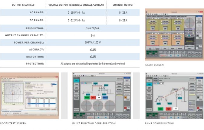
ROOTS (Relay Object-Oriented Test System) provides the best solution to the testing of today’s multifunctional IEDs by performing accurate fault calculation, sequential test execution, and reporting automatically. ROOTS is an optional product for PC-operation of SMC’s Mentor 12 and TRES relay test sets. ROOTS is developed using the latest Microsoft .NET® technology and is available for 32-bit and 64-bit Windows XP or later platforms. ROOTS includes also a powerful graphical editor, which allows representing the operating characteristics of IED in minutes, easing the test process. It includes a click & test method and also automatic generation of the test points list, with immediate test report generation.
-The best solution to the testing of today’s multifunctional IEDs
-Spans the testing from the relay to its interactions with the whole protection scheme
-Accurate fault calculation and sequential test execution
-Automatic, customized, and exportable Reporting
-Roots storage files are self-contained databases: relay data, characteristics, custom formulas, test routines, and report definitions
-Database management functions for the import/ export of device (relay), test definitions, and results between databases.
-The ability to use formulas instead of fixed values when entering test values, settings, options, or other data.
-Direct import of RIO relay description files supplied by a number of relay manufacturers.
-Intuitive graphical zone and elements Characteristics Editor, with pre-defined Templates.
-Modular architecture, different optimized test modules for each protection function.
-Modular pricing, ROOTS can be purchased with one or more functional modules, providing a price optimized solution
-Free updates, No other product in its class offers free lifetime updates and the possibility of being upgraded (in software and in hardware) by the user himself.
ROOTS implements an intuitive and friendly interface for the quick and accurate test configuration.
-Allows the configuration and storage in the database of the different devices, the test modules, test results, and test reports.
-Test routines and report definitions are saved according to a simple hierarchy that is flexible and easy to understand
-The database is organized by devices (IED), and the various test modules can be added to each device.
-Specific modules are available such as Distance, Differential, or Overcurrent, and also imports RIO files.
-Each test module contains a set of testing tools (click sequence, search, reclosing, breaker failure, etc.).
-In summary, substation/s overall test procedures can easily be built, can be repeated for maintenance testing, and also used as templates for similar substations with minimum adjustments, which saves considerable time.
The Smart Test Tool enables to automatically run of routine tests without the need of an external computer
-Capability to import RIO files.
-The tests are prepared in the ROOTS, then are stored in the USB memory, these then are read and executed directly with Mentor 12, without the PC.
-You can select and modify the binary inputs of Mentor 12 and the trip mode required.
-The results are shown graphically and numerically in the sequential list of test points.
-The results are automatically related to each test point and saved into a new file in the USB memory, and from here to the ROOTS database for immediate reporting when you are back at the office.
The Smart Test Tools is a perfect complement to the ROOTS software program, as it allows you to save your work plan in your pocket and run it on your Mentor 12, without manual intervention and without having to connect the equipment to a computer when in the field.
The PTE-100-C is used for maintenance work both in primary and secondary protections, in substations, transformation centers, as a multipurpose unit with a power of 1000 VA.
-Testing of single phase Current or Voltage Electromechanical and Electronic Relays.
-Current Transformer Test.
-Thermal Relays test.
-Measurement of different parameters such as Power, Phase Angle, Impedance, etc.
All the PTE equipment is supplied with adjustment and calibration software, which allows closed case calibration, with the only requirement of having a standard reference measurement equipment.
-Current output up to 250 A in 4 ranges
-AC voltage output from 0 to 250 V (4 A).
-DC voltage output from 0 to 350 V (2.8 A).
-Auxiliary DC power supplies up to 250 V.
-Built-in timer, 1ms resolution
-Output power: 1000 VA.
-Electronic protection in all outputs.
-Special control functions.
-Special measurement functions.
-Case: IP-65.
-Dimensions: 200 x 300 x 200 mm / 13.5 kg. 8 x 12 x 8 in / 30 lb.

Applications
-Increase load value.
-Improves current regulation.
-Improves output distortion.
-Obtain different angle values up to ±90°,
enabling to test directional relays.
Characteristics
-Resisters: 0.5, 1, 2, 25, 50, and 100 ohms.
-Mounted in the top cover
Applications
-Starts timer with external contacts, (NO) normally open/(NC) normally closed.
Characteristics
-Connected directly to monitor taps.
-Easily mounted and transported inside the unit.
-Dimensions: 90 x 120 x 60 mm / 0.4 kg. 3½ x 5 x 2½ in. / 1 lb
Applications
-Relay test requires variable frequency and phase angle, and independent voltage.
-Can be used with any existing PTE-100-C.
Characteristics
-AC voltage output up to 140 V.
-Frequency output from 40-70 Hz.
-Variable phase angle 0-359.9°.
-Easily mounted in the top cover.
-Built-in LCD display (PTE-FCN).
Characteristics
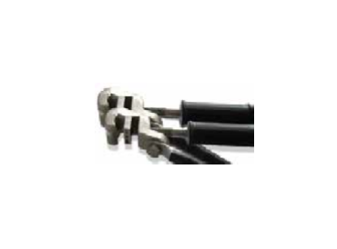
-To test MCB’s up to 250 A. Mounted in the cover of the PTE-100-C enables field testing of MCB’s of one or more poles up to 250 A.

Applications
-Enables to regulate the fixed voltage output of 110 V AC which is common in all the PTE-Range.
Characteristics
-Regulation range: 10 to 120 V.
-Maximum current: 0.3 A.
-Designed to be connected directly.
-Dimensions: 90 x 120 x 60 mm / 0.8 kg. 3½ x 5 x 2½ in. / 2 lb.
The PTE-100-C Plus is the combination of the basic PTE-100-C unit with the PTE-FCL option. This is incorporated in the lid of the equipment and generates voltage, frequency, and phase shifter independent of the current output.
-Single-phase testing of relays:
--Definite and inverse time over current.
--Min/max AC / DC voltage.
--Directional over current.
--Frequency.
--Distance.
--Synchronizing.
--Volts / Hz
--Directional power.
--Loss of Field.
--Reverse Phase.
--Negative sequence over current.
--Reverse phase / voltage.
--Thermal.
--Power factor.
--Overvoltage.
--Earth detection.
--Phase angle, Out of Step.
--AC / DC reclosing.
--Directional voltage and power
-Moulded Case Breakers (MCB, MCCB) testing.
- CT Knee-point analysis and many other accurate electrical measurements.
- Three-phase testing when combined with other PTE-range equipment
- Selectable power outputs:
--Variable AC current output up to 0-250 A.
--Variable AC voltage output up to 0-250 V.
--Variable DC voltage output up to 0-350 V.
- Variable auxiliary voltage supply 0-250 V DC.
- Variable AC voltage 0-140 V.
- Variable Frequency 40-70 Hz.
- Variable Phase Angle 0-359.9°.
- Isolated and electronically protected outputs.
- 1ms resolution chronometer
- External and internal signal measurement: voltmeter, ammeter, frequency meter, power meter, impedance meter, and phase meter.
- Injection time control limit.
- Maximum current output limit control.
- Output current preset function.
- RS-232 communications port.
- Interconnection with EuroSMC exclusive PTE-BUS.
- Case: IP-65.
- Dimensions: 200 x 300 x 200 mm. /15.5 kg. 8 x 12 x 8 in. /35 lb.
Description
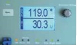
The PTE-100-C Pro combines the basic unit PTE100-C with the voltage supply module PTE-FCN. This is incorporated in the PTE-100-C cover lid, and allows, regulated AC voltage, frequency, and phase angle. The values which are presented in the LCD display are highly accurate, easy to read, and independent of the injection made by the PTE-100-C base unit. The display shows continuously the phase difference between the voltage and the current injected and can be adjusted during the test with an accuracy of 0.1º. This facilitates the test for directional relays or reclosers and synchronizing relays, etc. The protection tests based on frequency are simple and direct, due to the variable frequency between 40 and 70 Hz incorporated in the module. If you already have a PTE-100-C unit you can easily convert this to the PTE-100-C Pro with only adding the module PTE-FCN, at a low cost, without the need to send the unit to the factory
Testing of single phase Generation and Interconnection Relays, such as Frequency, Synchronizing, and Phase Angle. In combination with a current injector, forms a complete single-phase test set (Current Voltage, Phase Angle) to test Directional, Differential, Power, etc., relays
The characteristics of PTE-100-C Pro are the same as the PTE-100-C Plus, with the following specifications


The equipment has reversible outputs with a power of 100 VA for relays test in AC voltage or current with variable frequency and phase angle outputs
Testing of single phase Generation and Interconnection Relays, such as Frequency, Synchronizing, and Phase Angle. In combination with a current injector, forms a complete single-phase test set (Current Voltage, Phase Angle) to test Directional, Differential, Power, etc., relays

-Output power 100 VA.
-Variable voltage up to 300 V.
-Variable current up to 8 A.
-Variable phase angle from 0 – 359,9º.
-Variable frequency from 40 to 420 Hz.
-Internal program to ramp frequency.
-External frequency and phase reference input.
-RS-232 and PTE-BUS Connections.
-External timer control output.
-Monitor input to detect relay trips, dry or wet contact
-Internal program to perform dynamic pre-fault and fault in both output level and phase angle.
-Electronic generation up to 3 kHz isolated from the main supply
-Output stabilized by the microprocessor.
-Overload and thermal alarms, electronically protected.
-Case: IP-65.
-Dimensions: 200 x 300 x 200 mm. / 13.5 kg. 8 x 12 x 8 in. / 30 lb.
Reversible 100-VA current / voltage output with variable phase angle, digital chronometer and programmable harmonics generation.
Single-phase testing of electromechanical, static, and digital relays. Timing and assessment of protective elements based on voltage, current phase angle.
-100 VA output power.
-Variable current: 0.000
-50.00 A. - Variable voltage: 0.000 – 150.0 V.
-Variable phase angle: 00- 359.9º
-Digital programmable chronometer with 1-ms resolution
-Dry N/O, N/C, or voltage-charged operation contact detection
-Programmable dynamic pre-fault / fault step function.
-Harmonics generation from 50 to 420 Hz.
-Electronic overload and overheating protection.
-External synchronization signal input. - RS-232 communications.
-PTE Bus® for interconnection with other -PTE units. - IP-65 protective casing.
-Dimensions: 200 x 300 x 200 mm. / 13.5 kg. 8 x 12 x 4 in. / 30 lb.
Using the optional PTE-FCN module. Additional independent output channel with variable voltage, frequency, and phase angle. Extends the PTE-50-CE applications to protective elements with two voltage inputs or one current and one voltage input (e.g. directional, distance, overcurrent, synchronization, frequency relays, etc.)
-30-VA output power
-Adjustable voltage: 0.0 – 140.0 V
-Adjustable phase angle: 0.0 – 359.9º.
-Adjustable frequency: 40.0 – 70.0 Hz
-Digital high-contrast LCD display
-Installed inside the lid of the PTE-50-CE
-Dimensions: 200 x 300 x 200 mm. / 15.5 kg. 8 x 12 x 4 in. / 35 lb.
The combination of PTE-50-CE and PTE-100-V is used for testing single-phase relays and is interconnected via the PTE-BUS. To control both units simultaneously the equipment incorporates master/slave control for all outputs and levels. These small, lightweight units incorporate a built-in timer (PTE-50-CE) and a frequency generator (PTE-100-V). Each piece of equipment retains its individual characteristics and can be used together or separately for single and three-phase tests.
Testing of all types of single-phase relays whether they be electromechanical or digital, including differentials, synchronizing, directional, current, and voltage.
-2 reversible output channels in current or voltage, completely isolated, with individual phase angle control.
-Output power 100 VA in each channel
-Variable voltage up to 300 V and variable current up to 50 A.
-Variable phase angle from 0 - 360º.
-Variable frequency from 40 to 420 Hz.
-Internal program to ramp frequency.
-Built-in timer with a 1 ms resolution.
-Dimensions: 200 x 300 x 200 mm. x 2 / 13.5 + 13.5 kg. 8 x 12 x 8 in. x 2 / 30 + 30 lb.
The Battery simulator PTE-FCG is a simple and compact DC voltage to supply static and electronic relays when being tested. The equipment has a voltage supply with 3 DC output levels.
Provides an auxiliary DC voltage supply to the relay under test.
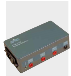
-Voltage output: 48/125/250 V DC.
-Power: 60 W in each output.
-Designed to be mounted in the top lid of the PTE Range of equipment or can be used as an independent unit.
-Dimensions: 110 x 180 x 60 mm. / 4 kg. 4 x 7 x 2 in. / 9 lb.
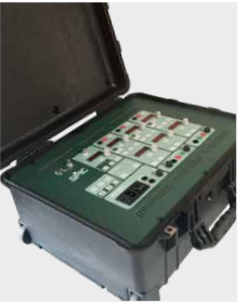
The equipment has 3 reversible outputs with a power of 100 VA for relays test in AC current or voltage with built-in timer and harmonic generator.
-Testing of three and single-phase
-Generation and Interconnection Relays.
-Testing of directional, differential, and power relays.
-Combined with a single-phase Current injection set enables relay tests that require three-phase voltages.
-Output power 100 VA x 3.
-Output power 300 VA single phase.
-Up to 900 V or 24 A single phase.
-The variable phase angle between 0 - 360º.
-Variable frequency from 40 to 420 Hz.
-Internal program to ramp frequency.
-External current or voltage reference input.
-RS-232 and PTE-BUS Connections.
-External timer control output.
-Monitor input to detect relay trips, dry or wet contact.
-Internal program to perform dynamic pre-fault and fault in both output levels and phase angles.
-Electronic generation up to 3 kHz isolated from the main supply.
-Output stabilized by the microprocessor.
-Overload and thermal alarms, electronically protected.
-Case: IP-65.
-Dimensions: 200 x 442 x 327 mm. / 22 kg. 8 x 18 x 13 in. / 48 lb.
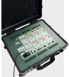
The equipment has 3 reversible outputs with a power of 100 VA for relays test in AC current or voltage with built-in timer and harmonic generator.
-Testing three-phase relays used in distribution networks and industry.
-Testing of three and Single Phase Motor -Protection and Thermal Image relays.
-Reversible outputs (Current Voltage, Phase Angle) make a complete single phase unit.
-Combining with other equipment can generate a complete three-phase system.
-Testing of directional, differential, and power relays.
This option enables to connect of 2 or 3 output channels of the PTE-50-CET in series to increase the voltage and power in the current output taps. In current mode requires optional plug PTE-SER to exceed 100 VA
-Output power 100 VA x 3.
-Output power 300 VA single phase*.
-Variable voltage up to 150 V x 3.
-Variable current up to 50 A x 3.
-Up to 150 A or 450 V single phase.
-The variable phase angle between 0 - 360º.
-Built-in timer with a 1 ms resolution.
-External timer control output. - External current or voltage reference input
-Harmonic generator.
-RS-232 and PTE-BUS Connections.
-Monitor input to detect relay trips, dry or wet contact.
-Internal program to make dynamic pre-fault and fault in both output levels and phase angles.
-Electronic generation up to 3 kHz isolated from the main supply.
-Output stabilized by the microprocessor.
-Overload and thermal alarms, electronically protected.
-Case: IP-65.
-Dimensions: 200 x 442 x 327 mm. / 24 kg. 8 x 18 x 13 in. / 52 lb
The combination of PTE-50-CET and PTE-300-V is used for testing three-phase relays and is interconnected via the PTE-BUS. To control both units simultaneously the equipment incorporates master/slave control for all outputs and levels. Each equipment retains their individual character and can be used together or separately for single and three-phase tests
Testing of all types of relays either manually or by software via computer.
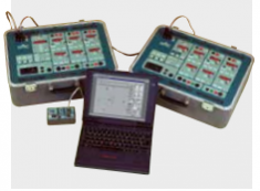
-6 reversible output channels in current or voltage, completely isolated, with individual phase angle control.
-Output power 100 VA x 6.
-Output power 300 VA* single phase both in current. and voltage
-Variable voltage up to 300 V x 3.
-Variable current up to 50 A x 3.
-Up to 150 A or 900 V single phase
-The variable phase angle between 0 - 360º.
-Variable frequency from 40 to 420 Hz.
-Internal program to ramp frequency.
-Built-in timer with a 1 ms resolution.
-External current or voltage reference input.
-RS-232 and PTE-BUS Connections.
-Manual control or software control of the 6 output channels.
-Overload and thermal alarms, electronically protected.
-Case: IP-65.
-Dimensions: 200 x 442 x 327 mm. x 2 / 22 + 25 kg. 8 x 18 x 13 in. x 2 / 48 + 52 lb

Applications
-Enables the control of the PTE equipment from a PC through an RS-232 serial port.
-Extraordinary flexibility as it can control up to 6 PTE equipment.
Characteristics
-Power is automatically supplied by the connected equipment.
-Includes all cables and connectors required.
-Includes the PTE-COM control command manual.
-Dimensions: 90 x 120 x 60 mm. / 0,5 kg. 3½ x 5 x 2½ in. / 1 lb.
Applications
-Enables to regulate the fixed voltage output of 110 V AC which is common in all the PTE-Range.
Characteristics
-Regulation range: 10 to 120 V.
-Maximum current: 0.3 A.
-Designed to be connected directly.
-Dimensions: 90 x 120 x 60 mm / 0.8 kg. 3½ x 5 x 2½ in / 2 lb.

Applications
-Enables to regulate the fixed voltage output of 110 V AC which is common in all the PTE-Range.
-To establish the moment of injection, the EUROFAULT software can be programmed to begin the test at the required time.
Characteristics
-Accuracy: <±1µs.
-Time until ready for operation: typically 3 min.
-Power supply: via PTE-BUS.
-Power consumption: 2W.
-Accessories: GPS antenna, PTE cable, box.
-Dimensions:
90 x 120 x 60 mm. / 0.5 kg.
3½ x 5 x 2½ in. / 1 lb.
Roots (Relay object-oriented test software) is the SMC response to the increasing complexity of the management and diverse testing methods with the modern numerical IEDs or protective relays. Roots have sophisticated preprogrammed features allowing the user to compose a complete test protocol by selecting them from a list. Each IED is registered in the database along with the test list and with its historical results, Roots can export data to a standardized information system for your test report in any format. Roots provide the engineer an innovative protective paradigm that allows expressing the testing process in terms of each type of protection (impedance, distance, differential, current symmetrical components, etc.) freeing you from complicated calculations, saving time, and eliminating errors.
As well a powerful graphical editor allows representing the IED operating characteristics in minutes thus facilitating the understanding of the tests, using the manual click & test methods, or allows the program to select test points and generate these automatically.

In the constant search of satisfying our customer’s needs and requirements, SMC found that many of our customers require modern and practical measuring test equipment, especially in the maintenance and commission departments, incorporating the characteristics and functions required by them.
SMC has been designing innovative and revolutionary products for electrical measurement tests. Our independent and traditional concepts in product and design, focus on the necessities of our customers.
Portability. Reduced size, weight, and robustness which is essential for field use.
Autonomy. Almost all this range of products have internal rechargeable batteries incorporated in the equipment. Therefore can be used without a voltage supply which is not always available in commissioning and substation work.
Integration. The use of microprocessors and other technical advances, enables the equipment to be multifunctional, as well as, avoiding errors and saving time.
Reliability and accuracy. The equipment is designed and produced with the latest technology and components, assuring accuracy and reliability. The Circuit Breaker Analyzer, which incorporates three-phase contact resistance measurements, is one of the examples that EuroSMC incorporates into our designs. All the new equipment designed by us in the past years have been leaders in the market.
The new GOOSEMeter is the answer to the tasks and applications that are required for the new substations, which demand new tools to make the work easier and more efficient.

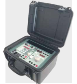
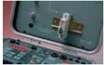
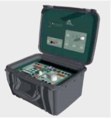
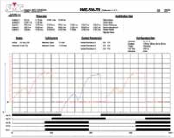
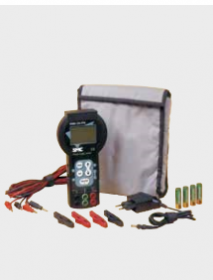
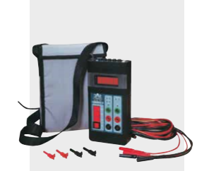
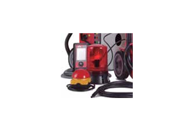
The PME-500-TR is small, lightweight, and standalone equipment with rechargeable batteries and it is easy to use. The current measurement of the coils, synchronizing time, and contact resistance measurement are made with an ultra-rapid microprocessor, which is extremely reliable and gives high accuracy. Tests are stored in the internal memory of the unit and are downloaded to a PC. The test results can also be exported to other programs such as MS Excel, etc.
-Simultaneous measurement for the 3 main contacts (open/closed) and 2 auxiliary contacts, including pre-insertion resistors (if present).
-Evaluates the synchronism between the circuit breaker poles.
-Determines the maximum currents, opening, and closing times in both coils simultaneously.
-Evaluates the state of the substation auxiliary batteries by graphically showing the coil consumption.
-Immediately displays and prints test results, both numerically and graphically.
-Automatically provides the contact resistance.

-3 timing inputs for the three main contacts, 0.1ms resolution.
-2 isolated auxiliary binary inputs, with a capacity for dry contacts or voltage signals up to ±360 V DC, 0.1ms resolution.
-Measures and records the Coil currents simultaneously (open and closed), with 1ms resolution up to 50 A DC (auto range).
-Connection to the breaker by means of a special multipole cable connector or by 4 mm input taps.
-Built-in thermal paper printer, 110 mm.
-Autonomous power supply with internal rechargeable batteries, up to 10 hours.
-Programmable operating sequences C, O, C-O, O-C, C-O-C, and O-C-O. Automatic measurement of the contact resistance, resolution 0.1 µΩ.
-Immediate graphic display of the test results.
-A Touch Screen panel (113 x 61 mm.) displays graphic images and is also the control of the unit.
-Allows the setup of the test data and test configuration from the touch screen panel (it converts into a complete keyboard).
-Software is supplied to download test results.
-Firmware can be upgraded via computer.
-Reduced size and weight.
-Dimensions: 340 x 300 x 150 mm. / 8 kg. 14 x 12 x 16 in. / 17.6 lb.


Optional Travel, Speed, And Acceleration Analysis Plug-In Module
The PME-TCE adds travel, speed, acceleration, and wipe data and graphics to the circuit breaker analysis report. This small module is powered from the PME-500-TR and provides connections for one analogue and three digital transducers. Results from multiple tests are saved in its flash memory and then downloaded to the PC by means of the USB connection.
-Digital inputs: 3 single-ended TTL, 5 V, 100 mA.
-Analogue input: 7.5 V, 10 mA.
-Communication: USB, PME BUS.
-Sampling frequency: 5 kHz per channel.
-Maximum recording time: 2 seconds.
-Dimensions: 148 x 89 x 25 mm. / 0,4 kg. 6 x 3½ x 1 in. /1 lb.
Movement sensors and mechanical adapters.

Rotary Transducer Kit, full angular measurement kit consisting of the digital angular encoder, articulated arm with magnetic stand, set of four-shaft adapter bushings, and hex key wrench.

Analogic Linear transducer of 500 mm.
Once connected to the substation’s IEC 61850 network, the GOOSEMeter One will immediately identify GOOSE messaging frames, will group them in their corresponding data sets, and will visually display the update activity on the screen. The GOOSEmeter one is a read-only device, so your network will remain safe against unwanted input. The collected data will be permanently stored in the device’s flash memory for later download from a Windows PC via the built-in USB port. The GOOSEMeter One’s operation is easy and intuitive, thanks to its touch-sensitive TFT display and the push/rotary encoder for fast navigation and selection.
-Event time, with microsecond resolution, of the last event.
-Identification and checking of GOOSE messages status, along with the historical list of changes.
-Shows in detail the list of data contained in the GOOSE message.
-Real-time inspection of IEC-61850 dataset lifecycle.
-GOOSE Filtering capability for monitoring only the selected data of interest.
-Templates editor, enables to personalize data names for easier identification.
-Discriminates datasets with different destination MAC addresses.
-Shows datasets with more than 64 data
-Firmware can be updated by the internet.
-High definition Touch Screen.
-GOOSESync for PC: Connectivity with an external computer, via USB, for downloading, analysis, and quick edition of templates.
-Dimensions: 110 x 184 x 26 mm. / 400 gr. 4 x 7 x 1 in. / 1 lb.
-No configuration, plug & run.
-Test in service.
-Read-only instrument.
-Not PC-dependent.
-USB storage.
-Handheld device to use in reduced spaces.
-Substation’s cabling verification.
-GOOSE message contents analysis.
-GOOSE monitoring with an online indication of the status change.

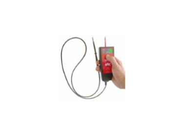
The phase angle meter is designed to measure the phase angle but also measures frequency, power factor, and it has an analogical scale that can be used as a synchronoscope.
-Measures the phase angle between two
Voltages, two Currents, or Voltage-Current.
-Measures Frequency.
-Measures Power Factor.
-Synchronoscope.
-In general, for Maintenance in Transmission and Distribution Systems, all well as industrial or commercial centers
- Phase angle accuracy: ±0.1°.
- Voltage input: 0.2 to 500 V RMS direct.
- Current input: 0.1 to 25 A RMS direct.
- Selected Measurement Modes:
Phase Angle displayed as ±180°.
Phase Angle displayed as 0 - 360°.
- Frequency: 40 to 500 Hz.
- Power Factor: 0 to ±1 and indicates phase angle quadrant.
- Battery Powered
- Reduced size and weight.
- Dimensions: 226 x 115 x 45 mm. / 650 gr. 9 x 4½ x 2 in. / 1½ lb.
-External adapter up to 750V RMS.
-Current clamp 1000/5A
This chronometer has been designed as an accessory to our injection instruments to test protective Relays. The PTE-30-CH can also be used as a standalone instrument
-Measures the trip time in protection relays and in general the lapse time between two events.
-Measures the time duration of electrical signals.
-Measures frequency.
-Start/Stop: time between two events.
-Pulse: measures the time of a signal pulse.
-Frequency: Reads the signal frequency at the input taps.
-Accuracy: ±0.01% ±1ms. -
-Dimensions: 190 x 100 x 40 mm. / 1 kg. 8 x 4 x 2 in. / 2.2 lb.
Measurement range: 3 modes S Mode: 00.000-99999s. Cycle Mode: 0000.0-9999.9 Cycles. Frequency Mode: 20.000-4000.0 Hz.
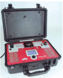
The Prime 600 is a micro-ohm meter that integrates both the contact resistance and the dynamic resistance measurement (DRM) as a stand-alone unit; the dynamic resistance test, which is essential in analyzing the wear of the arcing contacts in SF6 and vacuum breakers, is a function never found before in micro-ohm meters, so that with the Prime 600 is not required to combine several types of equipment for the complete static and dynamic resistance analysis, becoming an ideal option for circuit breaker testing. The Prime 600 draws the DRM time/resistance curve that describes the resistance changes on the measured spot throughout a few milliseconds, for detecting contact anomalies and wear; the analysis of the relevant characteristics and values of this curve is an effective diagnostic way of the internal condition of the breaker contacts and reveals potential problems related to the arcing contact condition without having to open the chamber. The Prime 600 micro-ohm meter provides easy and intuitive use with a touch screen and several pre-defined test modes, reducing the testing time; at the beginning of any test, the equipment checks for proper connectivity of the system, warning of possible connection mistakes; for increased safety, the Prime 600 demagnetizes the connected load at the end of each measurement.
-Dynamic Resistance Measurement
-Dual ground operation
-Automatic demagnetization function
-Alert on connection mistakes
-Touch-sensitive graphical display
-Pre-defined test modes
-Built-in thermal printer
-Removable USB storage
-PC download and reporting
-Sturdy, waterproof ABS casing, IP67
-Temperature normalization
-Power supply: 115/230 Vac – 50/60 Hz
-Dimensions: 47 x 35.7 x 17.6 cm
-Weight: 13.5 kg.


Enables the normalization of various resistance measurements to a common temperature value. The Prime 600 will capture the temperature reading and will calculate the normalized values for each test automatically.

When ground connections are in place at both sides of the measured spot, the Prime 600 will use this clamp’s reading to suppress the derived current value from the resistance calculation for an accurate result.
The maintenance and substation departments traditionally have found limitations when selecting primary injection test equipment. Either the equipment is a homemade brand with low reliability, poor accuracy at a low price, or a small selection of equipment with the accuracy and quality required, but at a high price.
SMC primary injection sets are a perfect solution, as the range of products is situated between the two options previously mentioned. The primary injection equipment manufactured by SMC is a large range of products that meet the power, current, and accuracy required for this type of testing.
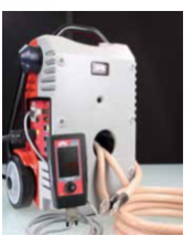
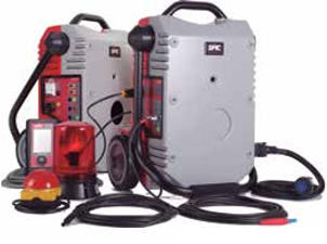
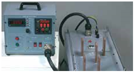
The Raptor System sets a new standard in the design of primary injection test equipment. Leading-edge technology and engineering have been combined to achieve small, but powerful and very portable equipment. This unit provides safer working conditions and also makes electrical maintenance more efficient and accurate, taking workability in Primary injection tests to levels never seen up till now.
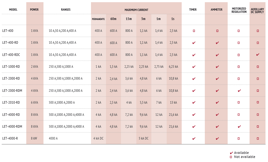
The LET range of primary injection test equipment is perfectly adequate to test current transformers, busbars, circuit breakers, switchboards, complete systems such as transformersrelays, and interconnections, with adequate technology and accuracy at an economic price. The large product range enables the selection of appropriate equipment required for the application required.

The Raptor system consists of a main ‘master’ unit and a number of optional units that enable the execution of virtually any commissioning or routine testing jobs on the primary equipment of medium and high voltage electrical installations. The massive use of digital technology and innovative design turns the Raptor system into the most portable primary test set available, at a very attractive price.
No matter the combination of master and optional units used, the entire Raptor system is controlled as a single device from the control console attached to the master unit. This small command center features a magnetic rear face and implements a comprehensive collection of pre-configured tests that can be customized and extended by the user. Custom settings and test results are permanently stored for subsequent download from a PC via a standard USB port. The Raptor console can be directly updated over the Internet via its built-in RJ-45 Ethernet® LAN connection.
The Raptor is a stabilized injection system, i.e. it will compensate small supply and load variations automatically to guarantee the test values throughout the entire job’s duration. Its compact and robust design enables the use of a single person, and its modular concept avoids the need of investing in unnecessary features or carrying equipment that you will not need.

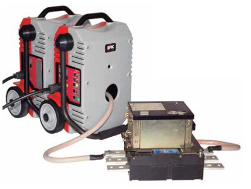
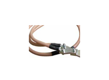
For high current applications, the Raptor implements the ‘pass-through secondary’ technique, with a centered hole that confers to this product a unique personality. You only need to drive the current conductor through the Raptor and attach both ends to the device under test. Multiple cables can be used in parallel to increase the effective cross-section, and the compliance voltage can be easily multiplied by just doing multiple turns around the unit. If additional power is required, 5-kVA slave units can be added for up to a total of 18 kVA and a maximum 15,000 A injection. These units communicate with the master Raptor via an infrared link, so no physical interconnections are required. An integrated software calculator allows determining the equipment and cabling required to attain a specific amount of currency easily.
Tests requiring a moderately high AC voltage of up to 2,000 V can be accomplished by adding the Raptor HV to the system. These jobs include power transformer evaluation, voltage withstand / isolation tests, and step & touch voltage measurement, among others. The Raptor HV is visually similar to the other Raptor units but lacks the characteristic center hole in the current injection models.
-Remarkably portable.
-Dynamic output stabilization.
-Multi-functionality.
-Expandability.
-Convenient and efficient pass-through technique.
-Pre-configured tests.
-Test & results storage, download, and reporting.
-Internet connection.

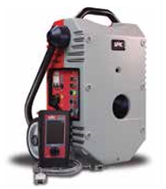
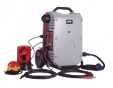
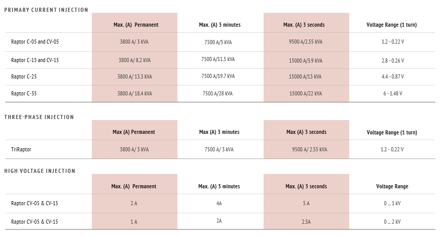
Every Raptor System needs one Master unit with the Raptor HH commander connected. This basic configuration is named Raptor C-05. It can be used stand-alone for high current testing and for most measurement applications. Add Current slaves to increase the injection power or one Voltage slave for moderate-to-high AC voltage test jobs.
Characteristics
3 kVA output power Handheld controller connection High current up to 9600 AAC Voltage up to 200 VAC Current, voltage, frequency and phase angle measurement inputs.

The current slave increases the Master unit’s compliance voltage for heavily demanding current applications. Especially appropriate for long injection cables or for current values greater than 9600 A. Up to three slaves can be added to one Master for configurations Raptor C-15, C25, and C35 respectively. Current slaves communicate with the master unit only via the built-in infrared link.
Characteristics
8 kVA power increase 15000 A max current IrDA link
Expands the Raptor System’s test capabilities to applications requiring up to 2000 VAC injection (power transformers, insulation tests, Step & Touch Voltage measurement, and more). Pre-defined test templates included in the Raptor’s standard repertoire. Optional accessories are available for special applications and added safety measures. The Raptor CV-05 configuration includes one Raptor C-05 system and one Raptor HV slave..
Characteristics
AC Voltage up to 2000 V Built-in ammeter Built-in alert buzzer Powered and controlled from the Raptor Master unit

High Current & High Voltage Injection
-Primary overcurrent testing of circuit breakers.
-Re-closer testing.
-Current and voltage transformer evaluation.
-Knee point calculation and graphic.
-Insulation testing.
-Testing of voltage sensors and converters.
-Step & Touch voltage measurement.
-Up to 9500 A AC output current.
-Up to 2000 V AC output voltage.
-Stabilized output.
-Outstandingly portable.
-Touch screen user interface.
-Factory- and user-defined test templates.
-PC download and reporting.
Internet connection.

Three- Phase Primary Current Injection

-Substation commissioning
-Three-phase primary switchgear testing
-Three current outputs at 0º-120º-240º
-Up to 9500 Aac - 3 kVA output power per phase
-Stabilized output
-Outstandingly portable
-Touch screen user interface
-Units can be used separately
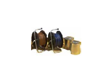
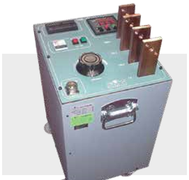
AC Current Injection Up To 2500A
-Primary current injection.
-Substation and transform center commissioning.
-LV, MV, and HV switchgear testing.
-Thermal protection testing.
-Current transformer evaluation.
-Permanent current up to 400A.
-Instantaneous current up to 2500 A.
-1 kVA output power.
-Four selectable output taps.
-Automatic overload protection.
-Built-in digital ammeter (RD and RDC models).
-Built-in digital chronometer (RD and RDC models).
-Variable 0-220 V AC an DC voltage output (RDC model).
-Auxiliary DC power source up to 220V (RDC model).
AC Current Injection Up To 6250 A
-Primary current injection.
-Substation and transform center commissioning.
-LV, MV, and HV switchgear testing.
-Thermal protection testing.
-Current transformer evaluation.
-Permanent current up to 1000A.
-Instantaneous current up to 6250 A.
-2 kVA output power.
-Three selectable output taps.
-Automatic overload protection.
-Built-in digital ammeter.
-Built-in digital chronometer.
AC Current Injection Up To 10800A
-Primary current injection.
-Substation and transform center commissioning.
-LV, MV, and HV switchgear testing.
-Thermal protection testing.
-Current transformer evaluation.
-Permanent current up to 2000A.
-Instantaneous current up to 10800 A.
-4 kVA output power.
-Four selectable output taps.
-Automatic overload protection.
-Built-in digital ammeter.
-Built-in digital chronometer.
-Two separately portable units.
-Motorized regulation in the RDM model.

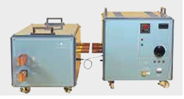
Primary Injection Test Set Up To 13,000A
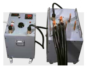
-Direct and motor overload relay test.
-In general, primary tests including the complete loop, such as current transformer, cables, protective relay, and circuit breaker.
-Permanent current up to 2000 A 6 kVA in 3 ranges.
-Maximum current output up to 13 kA.
-Made up of two units.
-Built-in digital ammeter 0.5% accuracy.
-Built-in digital timer resolution 1 ms.
-Thermal and short-circuit protection.
Primary Injection Test Set Up To 21,600A
-Direct and motor overload relay test.
-In general, primary tests including the complete loop, such as current transformer, cables, protective relay, and circuit breaker.
-Permanent current up to 4000 A, 8 kVA in 4 ranges.
-Maximum current output up to 21,6 kA.
-Made up of 2 units, a control, and a power unit.
-Built-in digital ammeter 0.5% accuracy.
-Built-in digital timer resolution 1 ms.
-Thermal and short-circuit protection.
-Motorized Variac.
High DC Current Injection Set
The LET-4000-R is an equipment designed for tests which requires High DC Current, used mainly in the railway industry for electric motors and extra fast relays
-For testing extra fast relays in DC current, mainly used in the railway industry.
-In general the use of any high DC current applications.
-DC Current output to 5000 A, 8000 W.
-Built-in digital ammeter, 0.5% accuracy.
-Built-in digital timer resolution 1 ms.
-Thermal and short-circuit protection
-Weight: 1 x 110 kg. /249 lb. y 1 x 75 Kg. /165 lb.
The ETP system is a set of equipment orientated to predictive maintenance in power transformers. The objective of all the equipment that makes up the system of predictive maintenance of transformer and rotary machines is to optimize the maintenance costs and to detect any faults before they occur. Also to manage the status of the machine to avoid and minimize any downtime.
The basic elements that are common to all the equipment are:
-Common control elements.
-Specific software for each application.
-Easy to follow, guided by software.
-Automatically stores and manages test results.
-Tendency analysis.
-Modular system is easy to transport.
-The results of the test in numeric values and graphically displayed, are automatically saved. When the test is finalized you can print and save test results for further analysis.
-The advantage of the system, and especially with three-phase transformers with tap changers, gives quick measurement results, obtaining simultaneously the simple and compounded values with external correction factors such as temperature. Therefore achieving savings in the test time not only the measurement time but also with results management and test report generation.

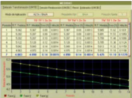
The ETP-1 module determines the turn ratio on the three phases of power and distribution transformers and autotransformers of any type by applying a test voltage on the high-voltage winding and measuring the resulting voltage on the low-voltage winding.
The ETP-1 equipment measures the following:
--Actual turn ratio for each position of the tap changer.
--No-load current and power, at the test
voltage.
--Polarity.
--Automatically calculates results according to with the connection group.
--Automatically creates a graphic comparison between the theoretic values and the values measured during the test for each tap position.
The ETP-1 can detect the following:
--Problems in the tap changer.
--Problems in the coils.
--Winding short-circuit.
--Defective contacts.
--Open circuits.
-The connection to the transformer taps is guided from the computer to avoid connection errors.
-Enables to select the number of the tap changer positions to be measured, as the software informs the position that should be measured each time.
-For each tap changer position, a three-phase automatic measurement is performed. It is not necessary to change the connection to the transformer taps.
-The no-load test current waveform is presented on the computer screen. It detects possible problems in the iron core.
-The test time for each three-phase test position is less than 10 seconds.
-The measuring range has a ratio between; 1:1 to 3000:1.
-Dimensions: 400 x 450 x135mm. /13 kg. 16 x 19 x 5 in. /29 lb.
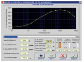
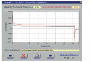
The ETP-2 module measures the recovery voltage on power and distribution transformers and autotransformers of any type with oil-paper dielectric, calculating the degree of humidity contained in the paper and evaluating the overall condition of the oilpaper.
The ETP-2 equipment measures the following:
--Recovery Voltage of the insulation.
--Insulation Resistance.
--Polarization Index.
To measure these parameters, the unit applies different levels of DC test voltage through an internal programmable voltage supply. The measured values are acquired automatically in the specified time. The equipment evaluates the actual general status of the insulation and detects possible aging problems in the quality of the paper/oil insulation.
The ETP-2 can detect the following:
--Solid dielectric degradation.
--Liquid dielectric degradation.
--Contaminated insulation.
- Fully automatic Recovery Voltage test in all the test cycles of voltage application and discharge of the insulation and measurement acquisition.
- Automatic generation of the measured values on each test cycle graphic representation.
- Results values are automatically corrected to a reference temperature enabling standard results.
- Numerical and graphic presentation gives the results of the following parameters:
--Recovery Voltage.
--Raising time of the capacity.
--Insulation Resistance.
--Time constant.
--Polarization Index
- The control program allows selecting the following possibilities to perform the insulation tests:
--HV + LV against ground
--HV against LV + ground
--HV against LV + Tertiary + ground, etc
--Dimensions: 400 x 450 x135 mm. /10 kg. 16 x 19 x 5 in. /22 lb.
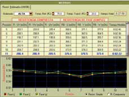
The ETP-3 is designed to measure very low resistance values on transformer windings or on any load with a strong inductive component. The unit applies the necessary DC current to magnetize the winding and stabilize the current, in order to provide an accurate, repeatable measurement.
The ETP-3 equipment measures the following for any type of transformer or autotransformer:
- Winding resistance value in single or three phases.
- Automatic correction of e resistance per phase to a predetermined reference temperature
- Automatic calculation of the compound winding resistance, for different configurations Delta, Star, etc.
- The ETP-3 can detect the following:
-Loose connections.
-Tap changer malfunction.
-Shorted turns.
-Hot spots on the windings.
-Performs the measurement of each phase, sequentially, without any change in the connection to the transformer, for each tap changer position.
-Software guided.
-Uses a four-wire measuring method.
-Automatic magnetization and de-magnetization of the iron core.
-Auto range from 1 mΩ to 1 KΩ.
-The test current range from 5 mA to 20 A is automatically selected.
-Automatic calculation of the resistance per phase.
-Immunity to variation in the values of the measurement circuit components, temperature changes, and changes in the test current.
-Dimensions: 400 x 450 x135 mm. /12 kg. 16 x 19 x 5 in. /27 lb.
The ETP-4 module measures the short-circuit impedance in distribution and power transformers by applying a test voltage on the high voltage winding and measuring the resulting current and phase angle.

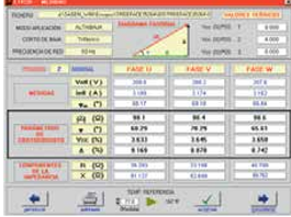
The ETP-4 equipment measures automatically the following for any type of power, distribution, or current transformer:
-Short-circuit Impedance measurement.
-Short-circuit current at the test voltage.
-Short-circuit power loss
The unit performs the test in a fully automatic way. The test voltage is generated through a motor-driven “variac”. This assures the repeatability of the successive tests in terms of the voltage application mode and avoids undesired risks due to sudden transients.
The ETP-4 can detect the following:
-Physical displacement of the transformer windings, due to electromagnetic efforts.
-Problems in the iron core.
-Transport damages.
-Fixation elements that may be broken.
-The software program guides the correct connection of the test cables on the primary winding and the short-circuits that must be done in the secondary (or tertiary) side, according to the specific connection group of the transformer under test.
-The software program recommends the tap changer positions that should be tested according to the maximum regulation % and the nominal tap.
-Displays and records the current and voltage waveform. This improves the diagnostic capability for further analysis.
-Dimensions: 400 x 450 x135 mm. /16 kg. 16 x 19 x 5in. /36 lb.
The ETP System is the combination of the equipment ETP-1, ETP-2, ETP-3, and ETP-4, along with the measurement, diagnostic and trend software, is a powerful tool for transformer maintenance and prediction based on the critical state of the transformer. The software ETP DiagHelp integrates the results of all the measurements obtained and applies to the knowledge base, which visually and directly indicates the critical and important information of the transformer which may require attention in the immediate or short-term future. The software ETP Trends is a historical register of the previous tests made and offers a visual evolution of all the factors analyzed, allowing a practical planning and maintenance integration avoiding costly downtimes or unnecessary substitutions. The ETP is designed for easy use and accuracy, a good inversion for predictive maintenance in power transformers.
Optional Multi-socket power surge protection
See ETP-1, 2, 3 and 4 previously mentioned
See ETP-1, 2, 3 and 4 previously mentioned
The EDA system is ideal for the evaluation and diagnosis of the insulation condition in electrical rotary machines such as motors, generators, alternators, etc. Its main function is to analyze the condition of the stator winding insulation, using DC voltage levels without risk to the element under test. The system obtains various parameters to evaluate the state of each of the components that make up the insulation in a rotary machine.
The following information is obtained from the EDA system:
-Insulation resistance (corrected to 20º and 40ºC).
-Polarization index.
-Absorption ratio.
-Leakage current.
-Standardized leakage intensity (voltage and capacitance).
-Leakage current ratio at each test voltage.
-Re-absorption current.
-Re-absorption current standardized for insulation thickness.
-Time constant.
-Initial reception and quality control of rotary machines (generators, alternators, LV, and MV motors).
-Forming a part of a maintenance program on rotary machines, where a non-programmed failure would represent a high cost, risks, and installation outage, and of course, to verify failures.
-To create a history of the motors tested as the EDA system generates a report. In this report, all technical data of previous tests are presented in a structured manner to easily follow the history of the element tested.
-To evaluate the parameters tested, anticipating failures, and diagnose the type of problem, thus planning in advance, the necessary maintenance steps required.
-Dimensions: 400 x 450 x135 mm. / 9 kg. 16 x 19 x 5 in. / 20 lb.

The testing of MCB’s enables the detection of the deviations in the characteristics and the quality control of these devices for the companies which manufacture or sells them. Random sample testing is required for MCB manufactures and is normally carried out by Utilities when purchasing large quantities. Testing those already installed in the Industry is also required.
A complete analysis is fundamental in determining, both independently and simultaneously, the characteristic of these devices with equipment that reduces testing time and has a stabilized current injection source, required by international standards. SMC has found that many MCB tests are made with homemade testing equipment, with unstable current sources, connected in series, resulting in unreliable test results and a limited capacity in the tests which can be made.
With this situation and the experience of SMC in AC current equipment, along with the demands of the market in MCB testing, the design of this range of products, required by users in this type of devices, is a product that is flexible to test various MCB’s, with different nominal values and different tests at the same time. The stabilized current generator along with software control gives reliable results. The system not only is capable of meeting international standards but also to those standards required in each country.

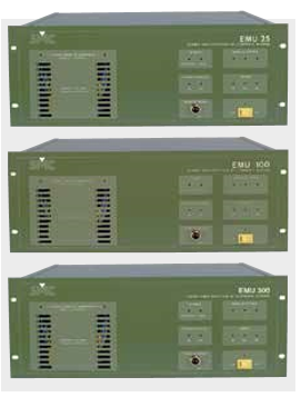
EMU-25
EMU-100
EMU-300
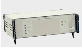
The EMU equipment is current power supplies that are computer-controlled. The principal function of these units is for laboratory testing which requires current injection of either short or long duration. The EMU units can be connected in parallel to achieve higher currents.
-Testing of small circuit breakers.
-Calibration of shunts and measurement instruments.
-Testing of thermic relays requires a long duration.
-Overheating test.
-Regulation:
-EMU-25: 0 - 25 A c.a.
-EMU-100: 0 - 100 A c.a.
-EMU-300: 0 - 300 A c.a.
-Nominal power: 300 VA.
-Can be connected in parallel.
Input for external phase and/or frequency reference.
-Computer-controlled
-Overload, overheating alarm LED.
-Rack mounting 19 inches (482 mm).
-Accuracy: ±1%. - Distortion: <1%.
-Dimensions: 482 x 175 x 370 mm. /30 kg. 19 x 7 x 14 in. /75 lb.
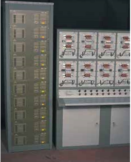
The SMC-12 system is designed to meet the needs established by the International Standards for the routine and quality control tests of Miniature Circuits Breakers (MCB) with regards to their Thermal and Magnetic response.
-Designed to test thermal and magnetic (Instantaneous) response of miniature circuit breakers (MCB’s).
-Meets the IEC 60898 - 2 requirements for testing MCB’s.
-Programmable testing unit, computer-controlled.
-Up to 10 simultaneous and independent test positions.
-Pre-selected current up to 100 A in each test position.
-Fully automatic operation.
-Records, stores, and prints all test results.
-Various tests can be performed at the same time.
-Different current values and brands of MCB’s can be tested at the same time.
-Can be connected in parallel to attain higher currents.
-Low current output distortion (<1%). Time measurement: Resolution 0.1 s.

Raptors Trading & Contracting has been established in February 2015 and it currently represents multiple reputable international brands. Our traditional business model is based on trading and contracting in the electrical engineering sector.
Quick Links
Contact Us
© Copyright 2026 Raptors Qatar. Proudly Powered by oxi-smart.net
WhatsApp us