
The reactive power regulators RPC are designed to provide the desired power factor while minimizing the wearing on the banks of capacitors, accurate and reliable in measuring and control functions are simple and intuitive in installation and consultation.
Automatic power factor regulator, which is only necessary to connect to display indicating measurements and integrated keyboard.
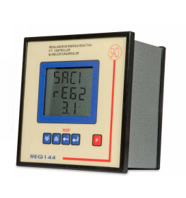
1. DIN144x144 INSTRUMENT
2. LCD DISPLAY
3.COS φ DISPLAY
4. AUTOMATIC SELF ADJUSTMENT FOR C/K VALUE
5.FOR CONNECTED CAPACITORS
6. RS485/RS232COMMUNICATION (optional)
ELECTRICAL PARAMETER | SYMBOL | L1 | L2 | L3 | TOTAL |
Voltage | V | - | - | - | |
Current (ref. to secondary) | A | - | |||
Active power (P) | kW | - | |||
Reactive power (Q) | kvar | - | |||
Apparent power (S) | kVA | - | |||
Power factor (Cos φ) | PF | - | |||
Frequency | Hz | - | |||
Connected steps | - | ||||
Operating program | - | ||||
Correct transformer connection | - | ||||
Transformer phase | - | ||||
Errors | - |
Mode1: Automatic
Automatically checks the connected capacitor steps, ( Automatic
self-adjustment for C/k value).
Prevents mistakes through poor current transformers or phase connection.
Mode2: Manual
1. LCD display with a built-in keypad.
2. Digit height: 14 mm
3.Selectable pages with up(↑)and down (↓) keys
Automatic power factor regulator, which is only necessary to connect to a current and the three-phase voltages, with the display indicating measurements and integrated keyboard.
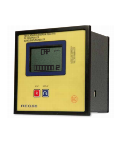
1. DIN 96x96 INSTRUMENT
2. LCD DISPLAY
3.COS φ DISPLAY
4. AUTOMATIC SELF ADJUSTMENT FOR C/K VALUE
5.AUTOMATIC STEP SETTING
6. FOR CONNECTED CAPACITORS
ELECTRICAL PARAMETER | SYMBOL | L1 | L2 | L3 | TOTAL |
Voltage | V | - | - | - | |
Current (ref. to secondary) | A | - | |||
Active power (P) | kW | - | |||
Reactive power (Q) | kvar | - | |||
Apparent power (S) | kVA | - | |||
Power factor (Cos φ) | PF | - | |||
Frequency | Hz | - | |||
Connected steps | - | ||||
Operating program | - | ||||
Correct transformer connection | - |
Mode1: Automatic
Automatically checks the connected capacitor steps, ( Automatic self-adjustment for C/k value). Prevents mistakes through poor current transformers or phase connection
Mode2: Manual
1.LCD display with built-in keypad
2. Selectable pages with up (↑)and down (↓) keys
Reactive power regulator measure cos φ and regulate the capacitor connection and disconnection to correct it.
1. 144 x 144 INSTRUMENT
2. LCD DISPLAY
3.COS φ DISPLAY
4.PROGRAMMABLE
ELECTRICAL PARAMETER | SYMBOL | TOTAL |
Cos φ value (inductive) | PF | - |
Cos φ value (capacitive | PF | - |
Nº of connected and disconnected steps | Hz | - |
Current value | - | |
Voltage value | - | |
THD value | - |
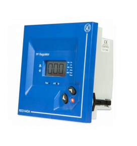
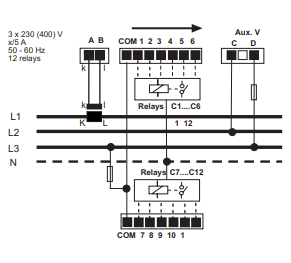
REG-144DA
1. 6 Output relays
2.12 Output relays
1. LCD DISPLAY
2. 1 line x 3 digits x 7 segments

Raptors Trading & Contracting has been established in February 2015 and it currently represents multiple reputable international brands. Our traditional business model is based on trading and contracting in the electrical engineering sector.
Quick Links
Contact Us
© Copyright 2026 Raptors Qatar. Proudly Powered by oxi-smart.net
WhatsApp us