
The AHM3 is designed to be used for the measurement and calculation of electrical variables such as voltage, current, frequency, power, power factor, energy, harmonic components, etc. in low, medium, and high voltage power distribution.
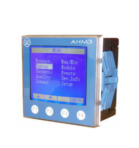
The AHM3 is designed to be used for the measurement and calculation of electrical variables such as voltage, current, frequency, power, power factor, energy, harmonic components, etc. in low, medium, and high voltage power distribution.
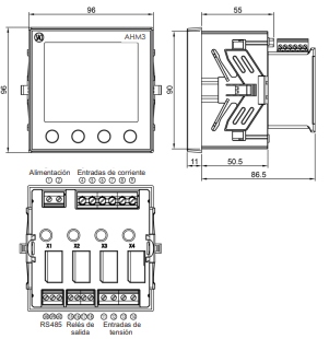
1.DIN 96 x 96 mm.
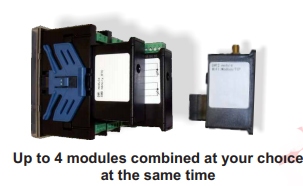
2. 13 ADDITIONAL MODULES.
3. 4 INTERFACES FOR MODULES.
4. THD on V and I.
5. HARMONIC RMS (1-63).
6. MAXIMUM DEMAND, A, kW, kVA, kvar.
7. MAXIMUM AND MINIMUM VALUES.
8. PROGRAMMABLE RATED V AND I.
9. 4 QUADRANT MEASUREMENT.
10. WAVEFORM.
ELECTRICAL PARAMETER | UNIT | L1 | L1 | L3 | TOTAL | MAX/MIN | DEMAND |
Voltage Phase - Neutral) | V, kV | - | - | - | - | ||
Voltage (Phase - Phase | V, kV | - | - | - | - | ||
Current | A, kA | - | - | - | - | ||
Neutral current | A, kA | - | |||||
Active power (P) | kW, MW, GW | - | - | - | - | - | - |
Reactive power (Q) | kvar, Mvar, Gvar | - | - | - | - | - | - |
Apparent power (S) | kVA | - | - | - | - | - | - |
Power factor (Cos φ) | PF | - | - | - | - | - | |
Frequency | Hz | - | |||||
Import active energy (EP+) | kWh, MWh, GWh | - | |||||
Export active energy (EP-) | kWh, MWh, Gwh | - | |||||
Reactive energy (Q1, Q2, Q3, Q4) | kvarh, Mvarh ,Gvarh | - | |||||
Backup energy | kWh | - | |||||
Hour meter | h: min | - | |||||
THD Current and Voltage | A, V | - | - | - | |||
Harmonic RMS-U and I (1-63) | % | - | - | - | |||
Unbalance -U and I | % | - |
It is capable of single-phase, two-phase, or three-phase measurement and can be used in two-wire, three-wire, four-wire, TN, TT, and IT systems. There are four interfaces on the meter for modules that are used to extend functions.
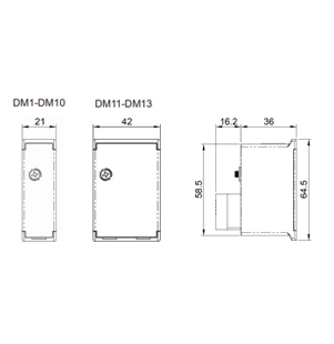
DM10 | Profibus-DP VO |
DM11 | Ethernet: Mobus/TCP |
DM12 | Wifi: Modbus/TCP |
DM13 | GPRS: Modbus/TCP, SMS |
DM6 | 2 digital inputs + 2 digital outputs |
DM7 | 4 digital inputs |
DM8 | 2 relay outputs |
DM9 | 1 AC digital input |
DM2 | 2 analog inputs: mA |
DM5 | 2 aanalog outputs: mA |
DM1 | Memory: 8MB, include RTC |
DM3 | 2 analog inputs: PT100 |
DM4 | 2 analog inputs: TC (J, K or E |

The ANG96 is a digital device, able to measure all the variables associated with an electrical line. It accepts the three currents and three voltage signals in a four-wire configuration. It is also possible to use it in a three-wire configuration, using two or three current transformers.
1.DIN SIZE 96 x 96.
2.LCD 128 x 64 DISPLAY WITH BACKLIGHT.
3.4 QUADRANT MEASUREMENT.
4.NEUTRAL CURRENT MEASUREMENT.
5.HARMONIC DISTORTION (THD on V and I).
6.MAXIMUM DEMAND (A, kW, kVA and kvar).
7.MAXIMUM AND MINIMUM VALUES.
8.TRUE RMS VOLTAGE AND CURRENT.
9.SERIAL PORT RS485.
10.2 HOUR COUNTERS.
ELECTRICAL PARAMETER | SYMBOL | L1 | L1 | L3 | TOTAL |
Voltage (Line-to-neutral) | V | - | - | - | |
Voltage (Line-to-Line) | V | - | - | - | |
Current | A | - | - | - | |
Neutral current | A | - | |||
Active power (P) | kW | - | - | - | - |
Reactive power (Q) | kvar | - | - | - | - |
Apparent power (S) | kVA | - | - | - | |
Power factor (Cos φ) | PF | - | |||
Maximum demand ( I ) | A | - | |||
Maximum demand (P) | kW | - | |||
Maximum demand (Q) | kvar | - | |||
Maximum demand (S) | kVA | - | - | - | |
Frequency | Hz | - | - | - | |
THD Current | A | - | |||
THD Voltage | V | - | |||
Import active energy (EP+) | kWh | - | |||
Hour counter active positive (T+) | h-m-s | - | |||
Export active energy (EP-) | kWh | - | |||
Hour counter active negative (T-) | h-m-s | - | |||
Import inductive react energy (Eq+) | kvarh | - | |||
Import capaitive react energy (Eq-) | kvarh | - |
2-hour counters:
- Active power + (consumed).
- Active power - (generated).
- Limit: 50.000 hours.
- Resolution: 1 second.
The maximum demand is calculated as the mean value
reached during the time specified of the next
parameters.
- I1, I2, I3, P, Q, and S.
- Integration period: 15 or 30 Minutes.
- 4 parameters per page.
- Built-in keypad ( 5 keys).
- Selectable pages with up and down buttons.
- Backlighting.
Contact outputs can be set as max. or min. alarm contacts associated with any measured parameter or as active energy and reactive energy pulses. They can also be set as contacts managed from the central unit.

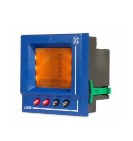
An instrument with microprocessor, programmable, with three, LED displays indicating measurements and a built-in keypad.
1.DIN 96 X 96 INSTRUMENT.
2. MEASUREMENT IN 4 QUADRANTS.
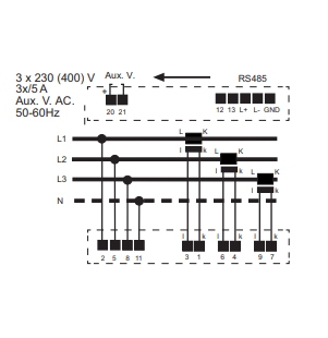
3.THREE-PHASE 3 or 4 WIRE.
4.NEUTRAL CURRENT.
5.HARMONIC DISTORTION (THD V and I).
6.HARMONIC MEASURING (up to 15) (optional).
7.MAXIMUM DEMAND A, kW, kVA.
8.MAX. and MIN. VALUES.
9.TRUE RMS.
10. RS485 SERIAL PORT.
11. 1 CONTACT OUTPUT.
ELECTRICAL PARAMETER | SYMBOL | L1 | L2 | L3 | TOTAL |
Voltage (Line-to-neutral) | V | - | - | ||
Voltage (Line-to-Line) | V | - | - | ||
Current and neutral current | A | - | - | - | |
Active power (P) | kW | - | - | - | - |
Inductive reactive power (QL | kvar | - | - | - | - |
Capacitive reactive power (QC) | kvar | - | - | - | - |
Apparent power (S) | kVA | - | - | - | |
Power factor (Cos φ) | PF | - | |||
Maximum demand ( I ) | A | - | |||
Maximum demand (P) | kW | - | |||
Maximum demand (S | kVA | - | |||
Frequency | Hz | - | |||
THD Current | A | - | - | - | 15th |
THD Voltage | V | - | - | - | 15th |
Import active energy (EP+) | kWh | - | |||
Import capacitive react. energy (EQC+) | kvarh | - | |||
Import inductive react. energy (EQL+) | kvarh | - | |||
Import apparent energy (ES+) | kVAh | - | |||
Export active energy (EP-) | kWh | - | |||
Export capacitive react. energy (EQC-) | kvarh | - | |||
Export inductive react. energy (EQL-) | kvarh | ||||
Export apparent energy (ES-) | kVAh | - |
*Contact output can be set as max. or min. alarm contacts associated with a measured parameter, or as active energy and reactive energy pulses.
Rated Voltage (Un) | 300 V (line to neutral) 520 V (line to line) |
Burden | < 0,7 VA |
Rated current (In) | 5 A |
Burden | < 0,75 VA |
Operating range | 0 - 110 % In |
Frequency | 45-65 Hz |
- Management software SACIgest.
- Reading software (without additional cost).
- LCD display with the built-in keypad.
- Height of digits: 8 mm (4 parameters per page).
- Backlighting.
2-hour counters:
- Active power + (consumed).
- Active power - (generated).
- Limit: 50.000 hours.
- Resolution: 1 second.
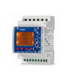
The instrument with microprocessor, programmable, LCD display indicating three measurements, and a built-in keypad.
1.MODULAR DIN INSTRUMENT.
2.MEASUREMENT IN 4 QUADRANTS.
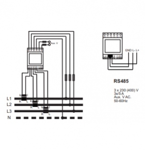
3.THREE-PHASE 3 or 4 WIRE.
4.NEUTRAL CURRENT.
5. HARMONIC DISTORTION (THD V and I).
6.HARMONIC MEASURING (up to 15) (optional).
7.MAXIMUM DEMAND A, kW, kVA.
8. MAX. and MIN. VALUES.
9. TRUE RMS.
10. RS485 SERIAL PORT.
11. 2 CONTACT OUTPUTS.
12. CURRENTS, 100, 250, or 500 A (t/e).
13.INTERNAL TEMPERATURE SENSOR.
ELECTRICAL PARAMETER | SYMBOL | TOTAL |
Voltage (Line-to-neutral) | V | - |
Current | A | - |
Active power (P) | kW | - |
Apparent power (S) | kVA | - |
Power factor (Cos φ) | PF | - |
Frequency | Hz | - |
Import active energy (EP+) | kWh | - |
Export active energy (EP-) | kWh | - |
Inductive reactive energy (EQ+) | kvarh | - |
Export inductive react. energy (EQL-) | kvarh | |
Capacitive reactive energy (EQ-) | kvarh | - |
*Contact output can be set as max. or min. alarm contacts associated with a measured parameter, or as active energy and reactive energy pulses.
Rated Voltage (Un) | 300 V (line to neutral) 520 V (line to line) |
Burden | 0,7 VA |
Rated current (In) | 100, 200 or 500 A |
Burden | 0,9 VA |
Operating range | 0 - 110 % In |
Frequency | 50-60 Hz |
- Management software SACIgest. - Reading software (without additional cost).
- LCD display with the built-in keypad.
- Height of digits: 8 mm (4 parameters per page).
- Backlighting.
2-hour counters:
- Active power + (consumed).
- Active power - (generated).
- Limit: 50.000 hours.
- Resolution: 1 second.
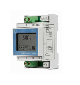
The instrument with microprocessor, programmable, LCD display indicating three measurements, and a built-in keypad.
1.DIN MODULAR INSTRUMENT.
2.SINGLE-PHASE.
3.TRUE RMS.
4. RS485 SERIAL PORT.
5. VALUE ALTERNATIVE MEASURE EVERY 4 S.
6. 1 OPTOCOUPLER OUTPUT.
ELECTRICAL PARAMETER | SYMBOL | L1 | L2 | L3 | TOTAL |
Voltage (Line-to-neutral) | V | - | - | ||
Voltage (Line-to-Line) | V | - | - | ||
Current and neutral current | A | - | - | - | |
Active power (P) | kW | - | - | - | - |
Inductive reactive power (QL | kvar | - | - | - | - |
Capacitive reactive power (QC) | kvar | - | - | - | - |
Apparent power (S) | kVA | - | - | - | |
Power factor (Cos φ) | PF | - | |||
Maximum demand ( I ) | A | - | |||
Maximum demand (P) | kW | - | |||
Maximum demand (S | kVA | - | |||
Frequency | Hz | - | |||
THD Current | A | - | - | - | 15th |
THD Voltage | V | - | - | - | 15th |
Import active energy (EP+) | kWh | - | |||
Import capacitive react. energy (EQC+) | kvarh | - | |||
Import inductive react. energy (EQL+) | kvarh | - | |||
Import apparent energy (ES+) | kVAh | - | |||
Export active energy (EP-) | kWh | - | |||
Export capacitive react. energy (EQC-) | kvarh | - | |||
Export inductive react. energy (EQL-) | kvarh | ||||
Export apparent energy (ES-) | kVAh | - |

Raptors Trading & Contracting has been established in February 2015 and it currently represents multiple reputable international brands. Our traditional business model is based on trading and contracting in the electrical engineering sector.
Quick Links
Contact Us
© Copyright 2026 Raptors Qatar. Proudly Powered by oxi-smart.net
WhatsApp us